Free weld sample evaluation — send us your part, we test-weld it before you commit.
HomeApplications › Solar Cell Tab Welding
Applications · Solar cell tab welding

Solar Cell Tab Welding

Solar cell tab welding attaches tinned copper tabbing ribbon to the silver bus lines on silicon wafers, connects the busbars between cells, and wires the junction-box lead-outs. Modern wafers sit under 150 µm thick, so mechanical and thermal stress both cause hidden micro-cracks. The temperature window is narrow — cold-joint high contact resistance on one side, wafer cracking on the other.
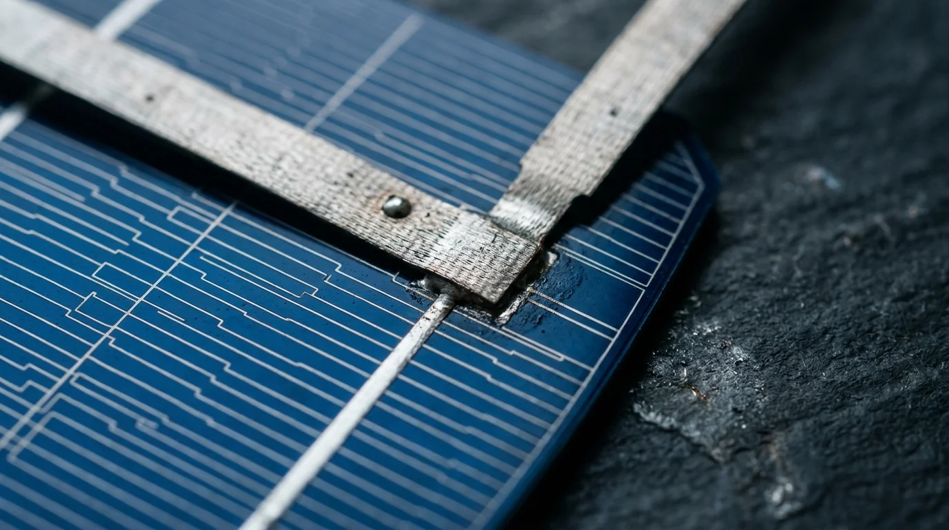
Corner of a dark blue silicon solar cell showing busbar patterns with a tinned metal interconnect tab ribbon welded onto the cell
Typical joints

Typical solar cell parts and joints

PV interconnection welding covers a recurring set of joints:

Process fit

Which process fits solar cell tab welding

Resistance / thermocompression (dominant)

The volume workhorse for tab-to-cell interconnection

Millisecond pulses under controlled force move heat through the ribbon into the bus line without soaking the wafer body — exactly what the narrow temperature window rewards. Capacitor-discharge systems tuned for cell interconnection are common, and wafer support tooling matters as much as the pulse recipe. See the resistance line →

Laser (selected cases)

MBB, SMBB and shingled-cell geometries

MBB and SMBB architectures use round wires that are hard to press against silver bus lines the way a flat ribbon can be pressed. Laser fits because it puts heat into a very small contact spot without needing significant force, and it handles shingled-cell overlap welds where wafer geometry constrains electrode access. See the laser line →

Pulse arc / Micro TIG

Not typically a fit for the cell itself

Arc heat sits above the silicon damage threshold; the wafer-crack risk is not worth the parameter effort. Junction-box side terminal welds occasionally reach into pulse arc territory; the cell interconnection does not. See the pulse arc line →

Because module output and long-term degradation both depend on this joint’s consistency, sample welds run through the customer’s EL inspection are the acceptance step that locks the process choice.

What’s hard

Common difficulties in solar cell tab welding

Four failure modes recur across PV cell interconnection programs:

Cell technology, ribbon width, bus geometry and EL inspection all shape the process window. The most reliable way to lock parameters for a specific cell architecture is a sample weld run through the customer’s own inspection flow. The evaluation is free.

Send a sample for free evaluation